10.13.1 Notes on fixing of CD loading section

TOP PREVIOUS NEXT

10.13.1.1 Notes on fixing of the select track

  1. Set a marking of a select drive gear at a marking of a mechanism base.

  2. Fix a select gear

  3. Slide a select track as shown by the arrow and fit it to a select gear.

  4. Draw up a select track at the edge of the rear side.

10.13.1.2 Notes on fixture of a vertical drive gear and GENEVA gear

  1. Fix a vertical drive gear, GENEVA gear, a vertical reduction gear, gears (2 pieces) and a relay gear.

  2. The marking should be at the position as shown below figure to fix a vertical drive gear.

  3. Set a hole as shown below to fix GENEVA gear.

10.13.1.3 Notes on fixing a vertical rack (L)

  1. Fix vertical rack (L) and (R).

  2. Position the concave portion of a vertical rack (L) to trapezoidal cog of a vertical rack (L) and fix.

  3. Fix a timing gear plate and a timing gear, then fasten them with screws.

10.13.1.4 Notes on fixing of a change gear and a main gear

  1. Fix a change lever and a change gear following 2. Then fix a level drive gear and a main gear spring, and fix a main gear following 3 and 4.

  2. Position a convex portion of a change gear to a marking of a mechanism base and fix.

  3. Position a hole of a main gear against a boss (a) of a mechanism base and fix.

  4. Rotate a main gear to the arrow direction to position a hole of a main gear to a boss (b).

  5. Draw up a select rack to the far front part.

10.13.1.5 Notes on fixing a pitch plate

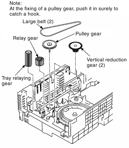
  1. Fix a reduction gear (2), a relay gear, a pulley gear, a tray relaying gear and a large belt (2).
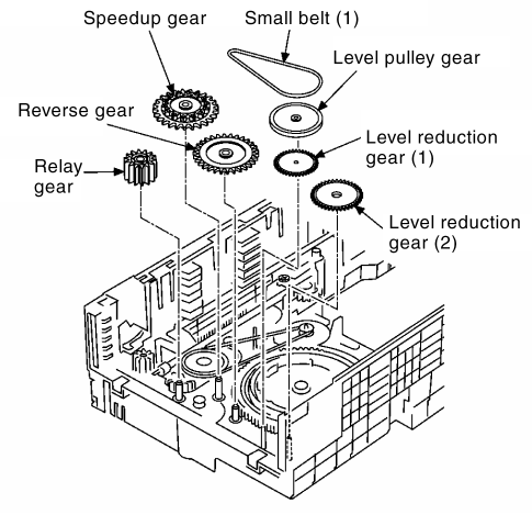
  2. Fix a level reduction gear (1), a horizontal reduction gear (2), a relay gear, a reverse gear, a speedup gear and a small belt (1).
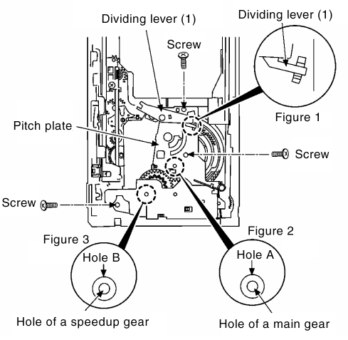
  3. Position the edge of a dividing lever (1) to the position shown in figure 1.

  4. The hole A of a pitch plate should be positioned at the hole of a main gear. (Figure 2)

  5. The hole B of a pitch plate should be positioned at the hole of a speedup gear. (Figure 3)

  6. Fasten with screws.

10.13.1.6 Notes on fixing a traverse mechanism

  1. Fix a vertical lever. (Fit a rib into both side grooves)

  2. Fit a traverse mechanism into the groove.

  3. The projecting portion of a dividing lever (2) should be inserted into a concave portion of a dividing lever (1).

  4. Set a loading gear at the position shown by figure 2.

  5. Draw a vertical rack (R) to the arrow direction.

10.13.1.7 Notes on fixing a disk tray

  1. Fix a tray drive gear and a tray drive gear shaft.
    (Position the lowest rib of a tray drive gear to be level)

  2. Move a tray guide (R) and a tray guide (L) to the arrow direction at a stretch, and fix disk trays (all of 5 pieces).

  3. Check the phase.

    1. The projecting portion of a dividing lever (2) should be inserted into a concave portion of a dividing lever (a).

    2. Seta loading gear at the position shown by figure 2.

    3. The hole A of pitch plate should be positioned at a hole of a main gear. (Figure 3)

    4. The hole B of pitch plate should be positioned at a hole of a speedup gear. (Figure 4)

    5. Set the bottom rib of a tray drive gear to be level. (Figure 5)

  4. Push in 5 disk trays simultaneously.

  5. Fix a speedup lock.

  6. Fix an open switch lever.
    (Insert a boss of an open switch lever into the hole of mechanism base)

  7. Fix a top cover.
    (Fix to the arrow direction after putting into the catch)


TOP PREVIOUS NEXT